My recent BLE project involves developing a custom peripheral profile for a 9 DOF sensor fusion embedded system with multiple sensors, such as accelerometer, gyroscope, magnetometer, and altimeter, etc. The system employs a nRF52 BLE module to transfer raw sensor data, plus calculated sensor fusion data, to a BLE central device, namely an iOS/Android mobile device, or a desktop computer with BLE capability, such as OSX or Windows 10 PC.
Softdevice is Nordic’s BLE stack implementation. The nRF52 softdevice is named s132. The project uses the recent nRF5 SDK version 11.0.0 released in March 2016 for development.
This version of SDK comes with version 2.0.0 softdevice s132.
By default, s132 supports one custom service and reserves memory for some characteristics. When you dig into the softdevice’s header files, you can find that reserved memory size is 0x580. My experiments tell me that amount of memory can support over one dozen of characteristics. That’s good in many situations, but not enough for my project, which requires 3 custom services and 42 characteristics, including many with notification.
Fortunately the softdevice is architectured in such way that it can be configured in runtime to meet application developer’s need.
There are couple of example projects in nRF5 SDK use multiple custom services, but there is none about expanding the reserved memory to support many more characteristics.
Hopefully my experience mentioned here is of useful for people needs more characteristics, and save some of their time to avoid troubles I had.
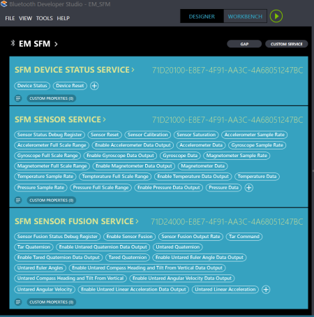
The screenshot below shows all services and characteristics of the custom BLE profile designed in BDS. BDS (Bluetooth Developer Studio) is Bluetooth SIG‘s design, development and testing tool. Many vendors, including Nordic and TI, provide BDS plugins. A vendor’s plugin can be used to generate certain code for its platform, saving tremendous amount of time for developers. For example, with this shown design, Nordic version 1.2.4 plugin generates 6,393 lines of code in multiple source files. Imagine how long it may take coding all of this manually. I will cover BDS in more details later in a separate blog.
Here’re the steps I used to configure the softdevice to meet the project requirement.
- Configure the count of custom services
According to Nordic programming convention, softdevice configuration is done in the following function:static void ble_stack_init(void)
To specify the number of supported custom services is easy. The following code snippet sets up 3 services:
ble_enable_params_t ble_enable_params; ble_enable_params.common_enable_params.vs_uuid_count = 3; - Configure the attribute table size
Set up attribute table size is trickier, and I don’t think Nordic provided any such example in nRF5 SDK.
In my instance, I added 0x700 more bytes of memory to support 42 characteristics. The reason is the default memory size of 0x580 supports 17 characteristics, and it supports 9 more characteristics after the size is adjusted to 0x800./* 0x580 added by 0x700 */ ble_enable_params.gatts_enable_params.attr_tab_size = 0x0c80;Here’s the complete function:
/**@brief Function for the SoftDevice initialization. * * @details It initializes the SoftDevice and the BLE event interrupt. */ static void ble_stack_init(void) { uint32_t err_code; nrf_clock_lf_cfg_t clock_lf_cfg = NRF_CLOCK_LFCLKSRC; // Initialize SoftDevice. SOFTDEVICE_HANDLER_INIT(&clock_lf_cfg, NULL); ble_enable_params_t ble_enable_params; err_code = softdevice_enable_get_default_config(CENTRAL_LINK_COUNT, PERIPHERAL_LINK_COUNT, &ble_enable_params); APP_ERROR_CHECK(err_code); /* * Supports 3 custom services */ ble_enable_params.common_enable_params.vs_uuid_count = 3; /* 0x580 added by 0x700 */ ble_enable_params.gatts_enable_params.attr_tab_size = 0x0c80; //Check the ram settings against the used number of links CHECK_RAM_START_ADDR(CENTRAL_LINK_COUNT,PERIPHERAL_LINK_COUNT); // Enable BLE stack. err_code = softdevice_enable(&ble_enable_params); APP_ERROR_CHECK(err_code); // Subscribe for BLE events. err_code = softdevice_ble_evt_handler_set(ble_evt_dispatch); APP_ERROR_CHECK(err_code); } - Configure the user application memory location and size
The last key step is to update the linker script to adjust the offset and size of the memory available to the BLE peripheral application.
I’m using GNU/Eclipse toolchain, the idea is the same when MDK or IAR is used.
Here’s the default MEMORY section’s RAM attribute values of the linker script:RAM (rwx) : ORIGIN = 0x20002080, LENGTH = 0xdf80
Here’s the modified values. Basically it moves forward the memory offset by the memory amount added (0x700), and reduce the available memory size by the same amount to make sure there is no overlap between softdevice and application memory regions.
RAM (rwx) : ORIGIN = 0x20002780, LENGTH = 0xd880
Note the up end of the RAM region is 0x20010000 (0x20002080+0xdf80, or 0x20002780+0xd880). Consider RAM origin starts at 0x20000000 for the softdevice, 0x10000 (64KB) is exactly the size of nRF52 RAM.
Here’s the complete linker script:
/* Linker script to configure memory regions. */

SEARCH_DIR(.)
GROUP(-lgcc -lc -lnosys)

MEMORY
{
  FLASH (rx) : ORIGIN = 0x1c000, LENGTH = 0x64000
  /* 0xc80 = 0x580 + 0x700 */
  RAM (rwx) :  ORIGIN = 0x20002780, LENGTH = 0xd880
}

SECTIONS
{
  .fs_data :
  {
    PROVIDE(__start_fs_data = .);
    KEEP(*(.fs_data))
    PROVIDE(__stop_fs_data = .);
  } > RAM
} INSERT AFTER .data;

INCLUDE "nrf5x_common.ld"
Nordic just released s132 softdevice v3.0.0 in August 2016, I will migrate soon and find out more details about the release.


