This is Part 3 for the topic.
In Part 2 – Quick Way, network connection and tftp server, plus certain knowledge of U-Boot are needed. You can avoid them by just using iMPACT to program the FPGA/SPI Flash. Here’s how.
On the host with Xilinx design tools installed, navigate to the folder with following files.
| File | Description | Usage |
| sopc_lx9.mcs | configuration data | program FPGA/SPI Flash |
| impact.cmd | programming script | for Xilinx USB II cable (6MHz) |
| impact.12Mh.cmd | programming script | for Xilinx USB II cable (12MHz) |
| impact.onboard.cmd | programming script | for Digilent Onbard JTAG |
Program FPGA/SPI Flash by running iMPACT in batch mode.
The Linux kernel and u-boot has a size about 10MB (still have some rooms left for 16MB Flash, I could see many potentials there), and FPGA/fs-boot has only 336KB. The final MCS data triples the size (in ASCII format).
It takes about 68 minutes on my Linux host, including verification. Program alone may take about 43 minutes, by using default JTAG clock speed, 6MHz.
With impact.12Mh.cmd, it takes about 35 minutes. iMPACT complains 24MHz is not supported.
I also tried several times to program by using MicroBoard’s Onboard USB/JTAG. It is supposed to be running fast (in 15MHz?). By 1) modifying Avnet Tom’s script listed in LX9 board forum Remarks on AvtS6LX9MicroBoard_SW302_PetaLinux, and 2) by iMPACT GUI, but I was never able to go to the end. I remembered once I let it run overnight from GUI, it was less than half way through in the next morning, and I had to abort the process.
It could be I didn’t specify options correctly. I attach the programming script for Onboard JTAG, just for reference, but be warned, don’t try it, it may take forever to program.
If you’re more interested at programming through iMPACT GUI to have a good understanding what’s going on, here’re some screenshots.
Start iMPACT by choosing “Configure devices using Boundary-Scan (JTAG)”.
Select “No” for “Auto Assign Configuration Files Query Dialog”.
Right click the device from “Boundary Scan” tab to add SPI Flash.
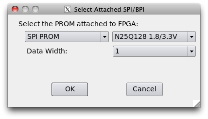
Select attached SPI Flash (N25Q128 1.8/3.3V).
Right click added SPI Flash device and select “Program”.
It achieves identical result as running the script in batch mode, and takes about the same time to finish.
If you’re interested, here’s the link for scripts and configuration data.


Leave a comment